


Toyota Prius PHV (ZVW 52), On-Board Charger Benchmarking Report
2017/08/16
Summary
The on-board charger on Toyota’s new Prius, launched in February 2017, is supplied by Toyota Industries Corporation. The output power transmitted to the battery is circa. 1.7 times as high as its predecessor. Owing to its unique control method to minimize the loss at conversion from AC to DC, high charging efficiency is achieved. It is also downsized by approximately 50% by means of integration of the charging system into ECU and of the improved cooling performance. The full report includes full of contents - the layout of each layer about the internal four circuit boards, an analysis of each layer layout, the circuits, the cross-section structure, measurement of the insulation distances between high-voltage portions and heat radiation images of the product, thus separated into 3 sub-reports. This article shows some of representative pages to provide an outline of the whole reports.
Table 1 Product information
| Vehicle information | Vehicle manufacturer | TOYOTA |
| Vehicle model name | PRIUS | |
| Vehicle type approv. code | DLA-ZVW52 | |
| Grade | - | |
| Full approval code | - | |
| Launched year | February, 2017 | |
| Engine | Hybrid-dedicated | |
| Engine type | 2ZR-FXE | |
| Displacement [cc] | 1797 | |
| Cylinder layout | Water-cooled inline 4-cylinder | |
| Valve train configuration | DOHC |
Product information
 |
| Supplier: Toyota Industries Corporation |
| Dimensions | Weight | |
| Product description | (W)300.3mm (L) 229.6mm (H) 80.2mm |
5.6kg |
| Number of cells | Voltage | Energy storage | |
| Lithium-ion battery | 95 cells (series) | 351.5V | 8.8kWh |
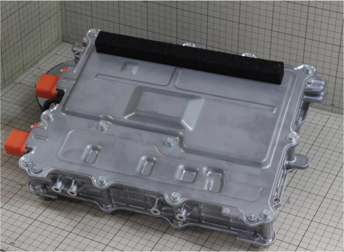
1.About the product
The analyzed product consists of a metal case made of metallic front cover/housing /back cover, an air cooling fan, four circuit boards and electric components installed outside the circuit boards which are power modules, reactors, bus bars, inductors, transformers and diode modules. During operation, the metal case is cooled by the air cooling fan. The power supply to the air cooling fan is located outside the product.
The connections to the externals of the product are constructed with connectors for the AC power supply, for the vehicle battery and for external communication /control.
The following three ways are prepared for charging to the vehicle :
- AC100V
- AC200V
- Quick charging
The on-board battery charged with the above ways has 3.7 V x 95 cells in series ( 351.5 V), referring to the main specifications of the vehicle the product is installed. The terminal voltage is estimated to be between 351 and 399 V at full charge.
The circuit boards are connected one another with flexible cables. Components installed outside the boards are connected by terminal-to-terminal crimping.
Table 2 Circuit board overview
| Power supply circuit board | Dimensions and area | (W)204.4mm multiplied by | (L)137.7mm = | 281.5cm2 |
| Number of layers | 4 layers | |||
| Board thickness | (t)1.7mm | |||
|
Control circuit board |
Dimensions and area | (W)245.3mm multiplied by | (L)131.4mm = | 322.3cm2 |
| Number of layers | 4 layers | |||
| Board thickness | (t)1.6mm | |||
|
Filter circuit board |
Dimensions and area | (W)276.9mm multiplied by | (L)62.0mm = | 171.7cm2 |
| Number of layers | 4 layers | |||
| Board thickness | (t)1.7mm | |||
| Driver circuit board | Dimensions and area | (W)79.9mm multiplied by | (L)53.8mm = | 43.0cm2 |
| Number of layers | 4 layers | |||
| Board thickness | (t)1.6mm |
Related Report File


-
{{ ct_title }}


Loading...
 Japan
Japan USA
USA Mexico
 Germany
 China (Shanghai)
 Thailand
 India
India